Air Flow Rate Sensor Arduino
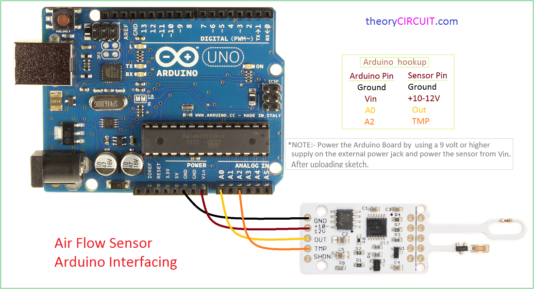
Air Flow Sensor Arduino Interfacing

Pressure Airflow Measure Device With Analog Sensor Arduino Project Hub

How To Measure Liquid Volume Flow Rate Sensor Arduino Youtube

Arduino Air Flow Rate And Air Pressure Sensor Youtube

Circuits4you Com Arduino Flow Measurement

Water Flow Measurement With Arduino Circuits4you Com
We know that this sensor will output a pulse to arduino pin 2 every time the flapper rotates and every and that every rotation means 2 25ml of fluid has passed the sensor so calculating the flow rate is really just a matter of counting the revolutions per minute and multiplying by 2 25ml.
Air flow rate sensor arduino.
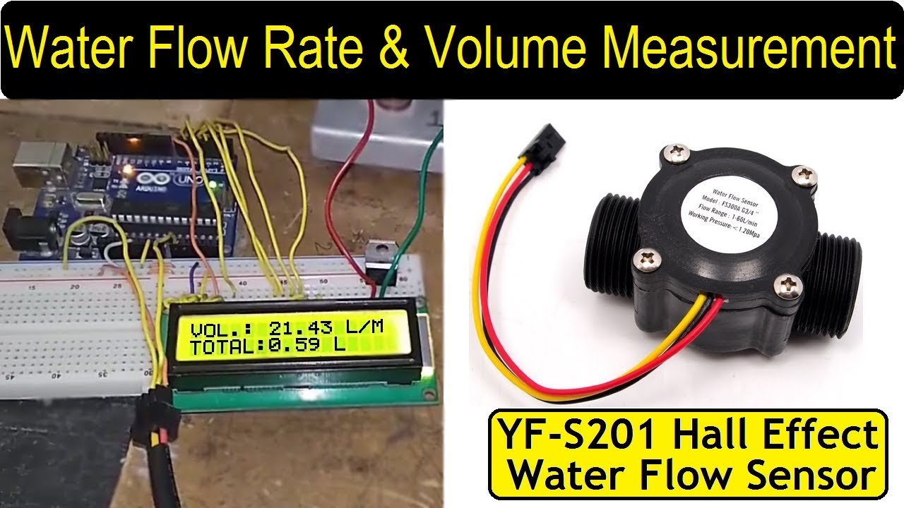
Water Flow Rate Volume Measurement Using Water Flow Sensor Arduino Youtube

Simple Air Flow Meter Korn S Open Source Tidbits
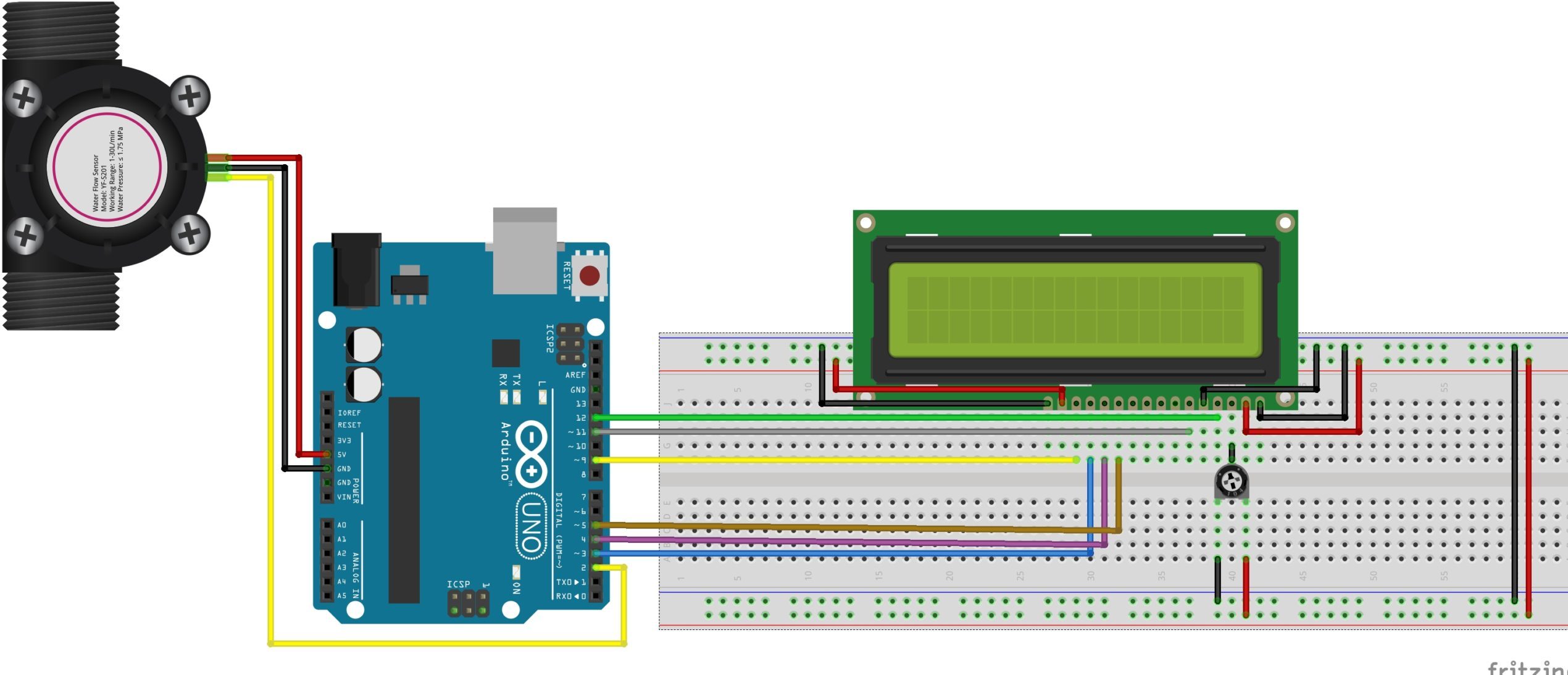
Measuring Water Flow Rate And Volume Using Arduino And A Flow Sensor Electronics Lab Com

Water Flow Sensor Measure On 16x2 Lcd Display Arduino Project Hub
Source : pinterest.com
